Principles of Electrostatic Measurements
The EPF sensor comprises a screened dual ring electrode system, installed into a stainless steel pipe (Fig.1 shows the industrial scale of this sensor). The electrodes are connected to a highly-sensitivity two-channel current to voltage converter (conversion steepness 10pA) and data acquisition system (16 bit resolution with a conversion rate of 2μs).
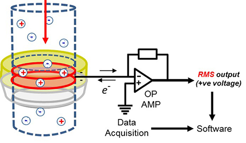
Fig.2. Schematic of the EPF sensor.
The electrodes act as capacitators which generate transient currants due to the net surface charges of particles flowing through each electrode (Fig. 1). In the schematic shown in Fig. 2, the positive net charge entering the sensing region (three positive charges and one negative charged particle) results in a negative bias on the electrode and a transient flow of current which is then registered as a voltage by the operational amplifier.
An electrostatic ‘noise’ spectrum is then generated by sampling this electrostatic signal at a rate of 2 kHz (i.e. 1 datum/ 0.5 mS).
The electrostatic signal is then synchronised with weighing measurements from an electronic balance (which records data at 20Hz) by calculating the deviation from the mean absolute electrostatic signal that is acquired between two consecutive weighing points and effectively determining a RMS data point every 0.05 seconds.
It is important to note that these values are not true RMS measurements, as that involves taking the squaring the individual voltages in a period and then finding the average before taking the square root, which would be a time consuming process and therefore unsuitable for real-time measurements. The average deviation from mean of the absolute signal is used as a substitute but we have retained the term RMS as a convenient terminology.

Fig.2. Raw induced and absolute induced electrostatic signal
as a function of time, with illustration of how RMS is derived